ATMEGA16
Assembling Code For And Flashing An ATmega16A
In this article we will see how to assemble a program for the ATmega16A
micro controller and flash it (write our binary to the micro
controllers memory so it can execute it.) We will also see how the
program works (it is a very simple program.) Our system is running
FreeBSD however the instructions should be generally applicable to any
other BSD or Linux distribution.
We will need an
ATmega16A, breadboard, 5v PSU (at least for the 16A), USBASP
v2.0 programmer (other programmers could be used) and of course
electronic components (LEDs, resistors, wires, etc,..)
Although the English is not the best we found this1 to be a good quick overview of our ATmega16A, for a much more complete reference see this2
Installing An Assembler
First we need to install an assembler. An assembler is a program
that will translate a program written using instruction mnemonics
to machine code (in reality it does a bit more then that, but it
effectively performs substitution with some small amount of
translation.) See this3 for a more complete and competent
explanation.
Our choice of assembler is avra (this was our choice because it was available.) We install avra by first searching for anything matching avr with "pkg search avr", this returned the following results:
arduino-avrdude-6.3_3          Program for programming the on-chip memory of Atmel AVR Arduino CPUs
avr-binutils-2.32_1,1          GNU binutils for AVR cross-development
avr-gcc-9.1.0                  FSF GCC for Atmel AVR 8-bit RISC cross-development
avr-gdb-7.3.1_6                GNU GDB for the AVR target
avr-libc-2.0.0_2,1             C and math library for the Atmel AVR controller family
avra-1.3.0_1                   Macro Assembler for Atmel AVR microcontrollers
avrdude-6.3_3                  Program for programming the on-chip memory of Atmel AVR CPUs
avro-1.9.0                     Data serialization system
avro-c-1.9.1                   C library for Apache Avro
avro-cpp-1.9.1                 C++ library for Apache Avro
libpololu-avr-151002_1         Support libraries for Pololu robots
py27-avro-1.9.1                Data serialization system for python
py36-avro-1.9.1                Data serialization system for python
rubygem-avro-1.9.1             Ruby library for Apache Avro
simavr-1.3_1                   Simulator for several Atmel AVR chips
We see the avra assembler and install it with:
doas pkg install avra-1.3.0_1(of course here one could use sudo in place of doas, or just be root.)
The M16Adef.inc File
We need to include m16Adef.inc in our program (this file specifically is for use with the ATmega16A with avra, there is another assembler avr-as.) I found the .inc file here4. .inc files for other Atmel controllers can also be found at that link, these .inc files contain useful definitions.
For some reason a couple of the lines in the m16Adef.inc file cause fatal errors when trying to assemble our code. We comment out the line (47), which causes the following error:
./include/m16Adef.inc(47) : Error : Unknown device: ATmega16AThe second error is caused by a line that is too long because of a comment (this comment is somewhere around line 533), so we breakup the comment at the end of this line so that it spans multiple lines. We can now assemble our program.
We think that our m16Adef.inc file might be intended for use with a different version of our assembler. We found the following on a forum thread5 regarding this issue (our version of m16Adef.inc is about 30K): "Note that one is about 10K and one is about 30K. I think avra is compatible with the original Atmel assembler (which uses the 10K versions) and not Assembler2 (which uses the 30K version).
I'll bet the file you are trying to use with avra is the 30K one. Suggest you get AVR Studio, install on a Windows machine or using wine (or a VM) in Linux then extract the copy you need (which probably violates the licence but you'll have to battle with your own conscience over that one!)
Cliff"
We will keep using our fix however since it seems to be working fine for the most part and we only had to change one line that was not a comment.
Assembling The Program
We assemble the following code with the following command:
avra hello.asm ;; Turn on an LED which is connnected to PC0
.include "./include/m16Adef.inc"
ldi r16, 0b00000001
out DDRC, r16
out PortC, r16
Start:
rjmp StartThe following output is generated after executing the above command to assemble the above code:
AVRA: advanced AVR macro assembler Version 1.4.1
Copyright (C) 1998-2010. Check out README file for more info
AVRA is an open source assembler for Atmel AVR microcontroller family
It can be used as a replacement of 'AVRASM32.EXE' the original assembler
shipped with AVR Studio. We do not guarantee full compatibility for avra.
AVRA comes with NO WARRANTY, to the extent permitted by law.
You may redistribute copies of avra under the terms
of the GNU General Public License.
For more information about these matters, see the files named COPYING.
Pass 1...
Warning : No .DEVICE definition found. Cannot make useful address range check !
Warning : No .DEVICE definition found. Cannot make useful address range check !
Warning : No .DEVICE definition found. Cannot make useful address range check !
Pass 2...
done
Assembly complete with no errors (3 warnings).
Segment usage:
Code : 4 words (8 bytes)
Data : 0 bytes
EEPROM : 0 bytes
We see that there are a number of warnings of the same nature. We
couldn't find any information about these warnings but we think they
mean that we could use an address that is out of range. These warnings
may be related to the issues encountered with the m16Adef.inc file.
After assembling we end up with a number of files:
hello.eep.hex, hello.hex, hello.objWe are interested in the .hex file. This is what we are going to flash to our micro.
Flashing Our Micro
Now that we have assembled our program we would like to flash our
micro with the binary.
We need to install a program called Avrdude
to flash our micro. Again we search for this program using pkg search:
pkg search avrdudeWhich results in the following output:
arduino-avrdude-6.3_3 Program for programming the on-chip memory of Atmel AVR Arduino CPUs
avrdude-6.3_3 Program for programming the on-chip memory of Atmel AVR CPUsSince we are not using an Arduino we install Avrdude with:
doas pkg install avrdude-6.3_3Now that we have Avrdude installed we can flash our device, we use the following command:
doas avrdude -p m16 -c usbasp -P /dev/ugen0.2 -U flash:w:hello.hexThe meaning of the options are as follows:
- "-p m16" tells Avrdude that we are using an atmega16 device (ours being the atmega16A specifically)
- "-c usbasp" tells Avrdude that we are using a Usbasp flasher (ours being the USBASP v2.0 specifically)
- "-P /dev/ugen0.2" is the path to the device file for our flasher (note the upper case p)
- Finally "-U flash:w:hello.hex" tells Avrdude that we want to write the file hello.hex to our micro.
There is an option to set the baud rate, we leave it as the default.
How do we know what the correct device file for our flasher is?
Well there of course would be a much better way to do this but we
simply used the following commands (attaching our USBASP v2.0 flasher
after running the first command):
ls /dev/ > tmp0.txt
ls /dev/ > tmp1.txt
diff -p tmp0.txt tmp1.txtThe output of the last command should look something like this:
*** tmp0.txt 2020-05-02 22:40:25.595809000 +1000
--- tmp1.txt 2020-05-02 22:40:49.691898000 +1000
*************** ugen0.1
*** 119,124 ****
--- 119,125 ----
ugen1.1
ugen1.2
ugen1.3
+ ugen1.4
ugen2.1
ugen3.1
ugen3.2
We see a line with a "+", this is the device file we are looking for (note that this example is from a different machine so the device file name is different to the one used in the Avrdude command above.) The micro should be placed in the programmer like so:
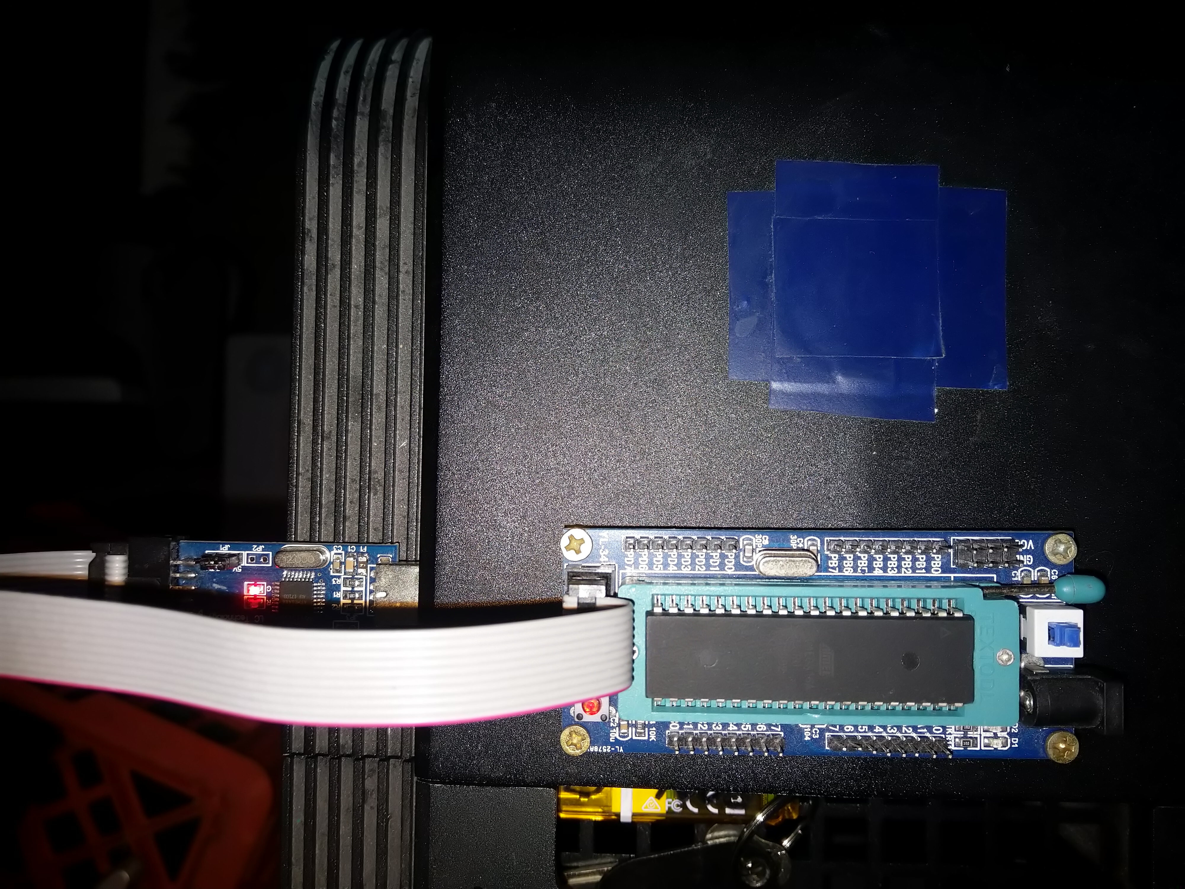
When we run the Avrdude command as described above we see the following output:
amethyst@dream:~/softDev/tmp/tmp2 % doas avrdude -p m16 -c usbasp -P /dev/ugen0.2 -U flash:w:hello.hex
Password:
avrdude: warning: cannot set sck period. please check for usbasp firmware update.
avrdude: AVR device initialized and ready to accept instructions
Reading | ################################################## | 100% 0.00s
avrdude: Device signature = 0x1e9403 (probably m16)
avrdude: NOTE: "flash" memory has been specified, an erase cycle will be performed
To disable this feature, specify the -D option.
avrdude: erasing chip
avrdude: warning: cannot set sck period. please check for usbasp firmware update.
avrdude: reading input file "hello.hex"
avrdude: input file hello.hex auto detected as Intel Hex
avrdude: writing flash (8 bytes):
Writing | ################################################## | 100% 0.08s
avrdude: 8 bytes of flash written
avrdude: verifying flash memory against hello.hex:
avrdude: load data flash data from input file hello.hex:
avrdude: input file hello.hex auto detected as Intel Hex
avrdude: input file hello.hex contains 8 bytes
avrdude: reading on-chip flash data:
Reading | ################################################## | 100% 0.06s
avrdude: verifying ...
avrdude: 8 bytes of flash verified
avrdude: safemode: Fuses OK (E:FF, H:99, L:E1)
avrdude done. Thank you.
Avrdude informs us that it "cannot set sck period." and that
we should "check for a usbasp firmware update." (our flasher
runs an Atmal it's self and evidently it's firmware needs updating, if
this message is anything to go by.)
The SCK period is the period of the clock pulses "which synchronize data transmission generated by the master"6
It seems our micro is being programmed via SPI.
The output shows that it has at least verified some of what was
written so it seems that it worked and of course this is verified when
we try out our newly programmed micro.
Circuit For Our Hello World Program And The ATmega16A
The micro requires 5V we use an ATX PSU (a bench power supply would
be preferable.) We hookup the green pin of the PSUs 24 pin connector to any of the black pins (this will turn on the PSU), for 5V we attach a wire to any of the red pins and for ground we attach a wire to any black pin. We note that the ATmega16A has internal pull up resistors on it's pins so we don't need to add any. For an explanation of pull up resistors see this7. Pin 10 is labeled VCC in the diagram below,
it is the pin we connect the positive side of our power supply to. VCC
stands for Voltage at the Common Collector
8
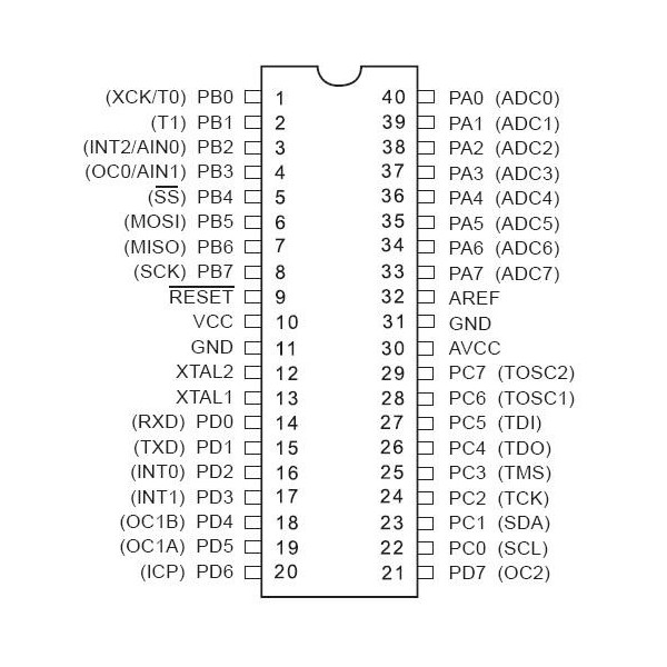
Pin 31 is GND AKA ground, it is the pin we connect the
negative side our power supply to.
Finally once we have our micro hooked up to our PSU we need to add the
LED. We connect the positive side of the LED (long leg) to PC0 (pin22)
of our micro. LEDs are current driven devices
9 and therefore we need a resistor to
limit current through the LED or it will burn out. We use a resistor
with a value of around 460 kΩ's. For more information on what
value to use see this
10.
The negative side of the LED (short leg) should be connected to the
resistor and the resistor should be connected to the ground side of
the PSU.
Finally we can power up our PSU and the following should be seen:
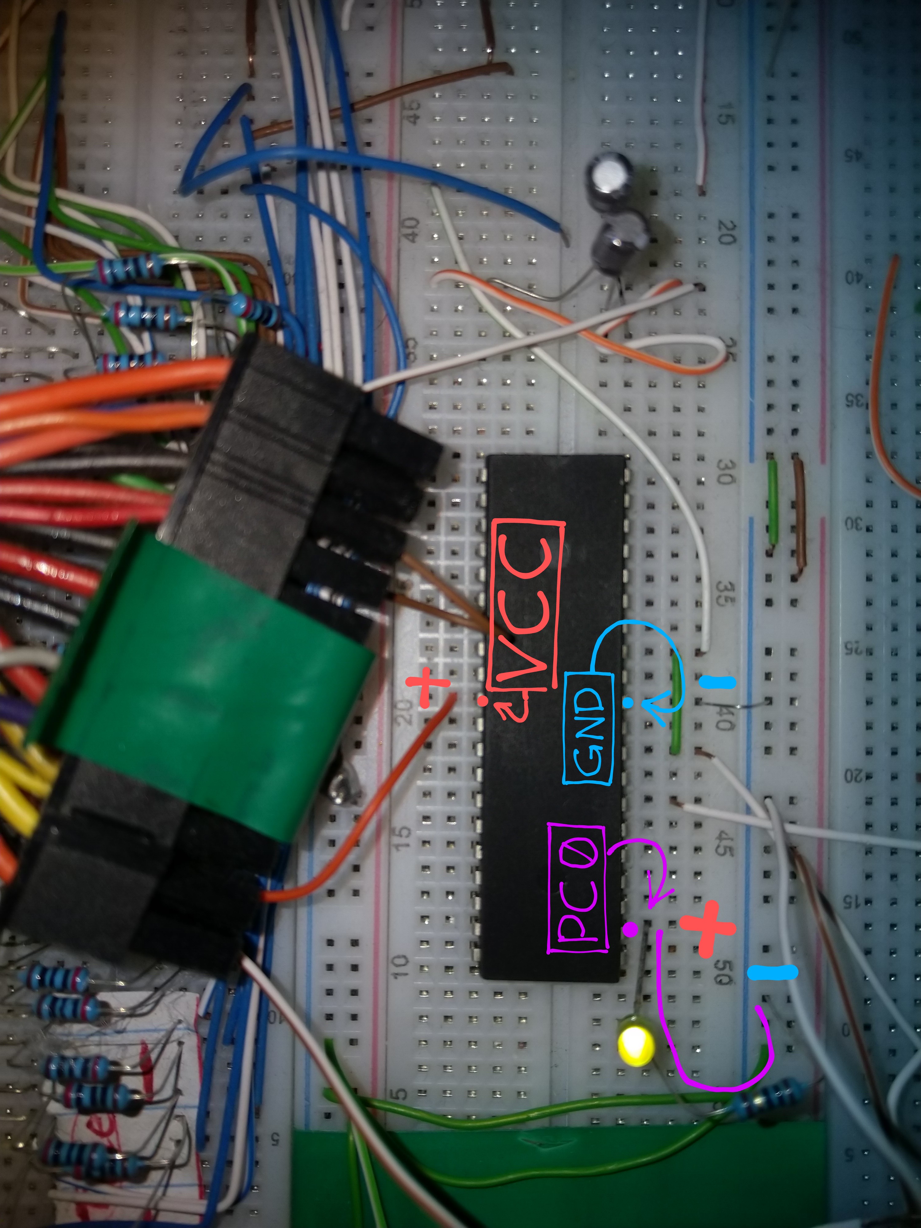
Note that there are a lot of extra unneeded wires and components in the image, these are not connected and are leftover from a project the author has been working on.
Program Details
Again we see the code for our program (below):
	;; Turn on an LED which is connnected to PC0

	.include "./include/m16Adef.inc"

	ldi r16, 0b00000001
	out DDRC, r16
	out PortC, r16
Start:
	rjmp Start
On the first line we see a comment.
On the third line we see an include directive. This includes the
m16Adef.inc file which contains useful definitions.
On the fifth line we see the first real instruction, namely
ldi. This mnemonic stands for load immediate. It loads the
register r16 (memory inside the CPU (Central Processing Unit) core that can be assessed with greate speed) with the value 0b00000001, the
registers are 8-bits wide. 0b is not part of the number, rather it is
a directive to the assembler to tell it that the following string of
characters should be interpreted as a binary number. The string of
course is 00000001 (1 in decimal.) The second argument to ldi
(0b00000001) is an immediate value, this means that it will be stored
after the ldi instruction in the text section of the executable (where
the instructions are stored.) This means that three memory accesses
will be required to read this instruction (assuming only one byte can
be read at a time and the ldi opcode (operation code) is one byte.
note that we define a byte to be one octet as is common.) One byte for
the ldi instruction opcode, one for the register address (in reality
if there is space the address of the register may be stored in the
same byte as the instruction opcode, meaning only two bytes would need
to be read), and one for the immediate value. The use of immediate
values means that we need less memory accesses. If we had have used a
memory address with the value at its location we would have to read in
the address and then dereference it. But with an immediate value
it's location is implicit and is relative to the location of
it's associated instruction opcode.
The next instruction we see is on line 6, this instruction is
out it outputs the value of a register to a port. In this
case the operands are DDRC and r16 and thus the port
is DDRC. DDRC is defined as 0x14 in m16Adef.inc. 0x indicates what
follows it (14) is a hex number, 20 in decimal in this case. Here we
see the value of the .inc file. Instead of having to write 0x14 (and
remember this value) for DDRC, we can simply write DDRC. What is DDRC?
DDRC stands for Port C Data Direction Register and it controls
whether the pins of port C (refer to the above diagram of the
ATmega16A to see which pins are associated with port C) are inputs or
outputs. We send an 8-bit number to DDRC and the value of each bit
determines whether the associated pin of port C is an input or an
output. the lowest order bit is associated with PC0 and the second
lowest order bit is associated with PC1 and so on. A value of 1
indicates an output and 0 indicates an input. In our case we sent the
value in r16 (00000001) to DDRC. This sets PC0 as an output and [PC1,
PC7] as inputs.
Next we see the instruction on line 7, it's opcode is out again.
The difference this time is that the first operand is changed to
PortC (from DDRC). PortC is defined as 0x15 in m16Adef.inc. The effect of this
instruction is to set any port C pins that are set as outputs to high
or low depending on the value of the corresponding bit in the value of the second operand (r16). Where a
1 indicates high and 0 indicates low. The high and low values are
roughly defined as 5V and 0V respectively.
Since the value of r16 is 00000001 and the only port C pin that is set
as an output is PC0 the effect of this instruction is to set PC0 high as the corresponding bit in r16 is 1 (this
turns on our LED.)
However we need one more instruction. The reason for this is that
the program counter (PC) AKA instruction pointer (IP) (a special register that
points to the next instruction to be fetched from memory) will
continue to be incremented and we don't know what lies beyond our
last instruction (it's possible to determine this, however
that's not very useful.) This would lead to possibly undefined and almost
certainly undesirable behavior. So we come to the last two lines
(8 and 9). Line 8 contains a label (Start). The assembler
will remember the position of this label in our code. The next line
contains the instruction rjmp with the operand Start.
Rjmp stands for relative jump and it will jump to an address that is
relative to the current PC value. Essentially it will add the value of
it's argument to the current PC (changing the address of the next
instruction that will be fetched.) This is known as an unconditional
branch. In our case the operand to rjmp is Start. Start is interpreted
as an address who's value is determined by the assembler. The
assembler sets Start's value to the address (relative to the address of
the rjmp instruction) of the instruction that follows the Start directive (this instruction being rjmp).
What all this means is that when our program is run the micro will read the rjmp instruction and it's opcode will be added to the current PC and in this case this will cause the PC to point to the rjmp instruction. This means once the code reaches the rjmp instruction it will loop indefinitly and PC0 will stay in the state it was last set to and our LED will stay lit.
- https://www.instructables.com/id/Command-Line-Assembly-Language-Programming-for-Ard/
- https://github.com/samcdc6600/ATmega16a-avra-asm-stuff.git
- https://avrlogic.blogspot.com/2014/11/programming-atmega16-led-blink.html
- https://artofcircuits.com/product/usbasp-v2-0-programmer-for-atmel-microcontrollers
References:
- https://www.theengineeringprojects.com/2018/06/introduction-to-atmega16.html
- https://www.mouser.com/datasheet/2/268/Atmel-8154-8-bit-AVR-ATmega16A_Datasheet-1065799.pdf
- https://en.wikipedia.org/wiki/Assembly_language#Assembler
- https://github.com/DarkSector/AVR/tree/master/asm/include
- https://www.avrfreaks.net/forum/problem-avra-avr
- https://www.arduino.cc/en/reference/SPI
- https://www.electronics-tutorials.ws/logic/pull-up-resistor.html
- https://acronyms.thefreedictionary.com/VCC
- https://forum.allaboutcircuits.com/threads/leds-are-current-driven.39855/
- https://www.instructables.com/id/Choosing-The-Resistor-To-Use-With-LEDs/
Date: 03/05/2020